|
|
| |
|

|
|
|
|
| |
|

|
| |
 |
Integrated Injection Logic
|
| |
|

|
|
|
TODO |
| |
|

|
|
|
|
| |
|

|
| |
 |
Emitter coupled logic
|
|
|
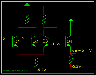
Emitter coupled logic (ECL) is a non saturated logic, which means that transistors are prevented from going into deep saturation, thus eliminating storage delays. Preventing the transistors from going into saturation is accomplished by using logic levels whose values are so close to each other that a transistor is not driven into saturation when its input switches from low to high. In other words, the transistor is switched on, but not completely on. This logic family is faster than TTL. |
| |
|

|
|
|
Voltage level for high is -0.9 Volts and for low is -1.7V; thus biggest problem with ECL is a poor noise margin. |
| |
|

|
|
|
A typical ECL OR gate is shown below. When any input is HIGH (-0.9v), its connected transistor will conduct, and hence will make Q3 off, which in turn will make Q4 output HIGH. |
| |
|

|
|
|
When both inputs are LOW (-1.7v), their connected transistors will not conduct, making Q3 on, which in turn will make Q4 output LOW. |
| |
|

|
|
|
 |
| |
|

|
| |
 |
Metal Oxide Semiconductor Logic
|
|
|
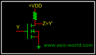
MOS or Metal Oxide Semiconductor logic uses nmos and pmos to implement logic gates. One needs to know the operation of FET and MOS transistors to understand the operation of MOS logic circuits. |
| |
|

|
|
|
The basic NMOS inverter is shown below: when input is LOW, NMOS transistor does not conduct, and thus output is HIGH. But when input is HIGH, NMOS transistor conducts and thus output is LOW. |
| |
|

|
|
|
 |
| |
|

|
|
|
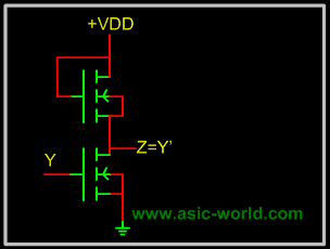
Normally it is difficult to fabricate resistors inside the chips, so the resistor is replaced with an NMOS gate as shown below. This new NMOS transistor acts as resistor. |
| |
|

|
|
|
 |
| |
|

|
| |
 |
Complementary Metal Oxide Semiconductor Logic
|
|
|
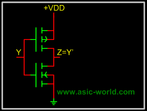
CMOS or Complementary Metal Oxide Semiconductor logic is built using both NMOS and PMOS. Below is the basic CMOS inverter circuit, which follows these rules: |
|
|
- NMOS conducts when its input is HIGH.
- PMOS conducts when its input is LOW.
|
|
|
So when input is HIGH, NMOS conducts, and thus output is LOW; when input is LOW PMOS conducts and thus output is HIGH. |
| |
|

|
|
|
 |
| |
|

|
| |
|

|
| |
|

|
|
|
|
| |
|

|
|
|
|

|

|

|
|

|
|
Copyright © 1998-2025 |
Deepak Kumar Tala - All rights reserved |
|
Do you have any Comment? mail me at:deepak@asic-world.com
|
|