|
|
| |
|

|
|
|
|
| |
|

|
| |
 |
Multipliers
|
|
|
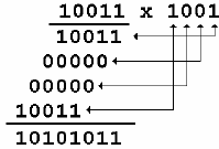
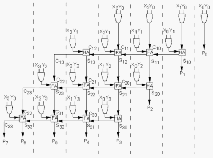
Multiplication is achieved by adding a list of shifted multiplicands according to the digits of the multiplier. An n-bit X n-bit multiplier can be realized in combinational circuitry by using an array of n-1 n-bit adders where each adder is shifted by one position. For each adder one input is the shifted multiplicand multiplied by 0 or 1 (using AND gates) depending on the multiplier bit, the other input is n partial product bits. |
| |
|

|
|
|
 |
| |
|

|
|
|
 |
| |
|

|
|
|
|
| |
|

|
| |
 |
Dividers
|
|
|
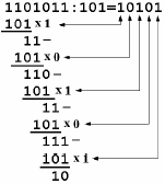
The binary divisions are performed in a very similar manner to the decimal divisions, as shown in the below figure examples. Thus, the second number is repeatedly subtracted from the figures of the first number after being multiplied either with '1' or with '0'. The multiplication bit ('1' or '0') is selected for each subtraction step in such a manner that the subtraction result is not negative. The division result is composed from all the successive multiplication bits while the remainder is the result of the last subtraction step. |
| |
|

|
|
|
 |
| |
|

|
|
|
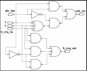
This algorithm can be implemented by a series of subtracters composed of modified elementary cells. Each subtracter calculates the difference between two input numbers, but if the result is negative the operation is canceled and replaced with a subtraction by zero. Thus, each divider cell has the normal inputs of a subtracter unit as in the figure below but a supplementary input ('div_bit') is also present. This input is connected to the b_req_out signal generated by the most significant cell of the subtracter. If this signal is '1', the initial subtraction result is negative and it has to be replaced with a subtraction by zero. Inside each divider cell the div_bit signal controls an equivalent 2:1 multiplexer that selects between bit 'x' and the bit included in the subtraction result X-Y. The complete division can therefore by implemented by a matrix of divider cells connected on rows and columns as shown in figure below. Each row performs one multiplication-and-subtraction cycle where the multiplication bit is supplied by the NOT logic gate at the end of each row. Therefor the NOT logic gates generate the bits of the division result. |
| |
|

|
|
|
 |
| |
|

|
| |
 |
Parity Circuit
|
| |
|

|
|
|
 |
| |
|

|
| |
|

|
| |
|

|
|
|
|
| |
|

|
|
|
|

|

|

|
|

|
|
Copyright © 1998-2025 |
Deepak Kumar Tala - All rights reserved |
|
Do you have any Comment? mail me at:deepak@asic-world.com
|
|